Sunday 22 December 2013

2013 in review, what's planned for 2014


Well It’s come to the end of another year so I thought I’ll give a review of the year of what’s happen and what’s planed for 2014.
2013 has been very busy outside of Bendigo, a house move, working lots of days and the birth of our daughter, time sure has disappeared. With all that happing not much was done on Bendigo. I was hoping to have most of the rail laid by now. However many parts have been design for etching which took a lot time. I had to spend a lot of time making up parts for the future to fill up the minimum A4 sheet needed for the etching house. Once that was done I them made the decision to do the etching myself. I’ve also have decided that some of the etch parts I will now get 3D printed, which will be better with detail and strength. So it was a wasted few months, but many things were learnt so there is still a positive to it.
Doing my own etching has been a great learning process. The first run didn’t quite work out, but I was still very happy with the result.  I’m now looking at a new etching solution that does not need to be heated. I’m in the process of getting these acids.  Having a non heated solution will be a lot easier to use and I will be able to build a simple etching tank.
What’s for 2014
The first thing for 2014 will be the construction of my new modelling desk.  This will be a purpose built desk that will give me plenty of room to work on all my projects. I normally have a few projects on the go at once, usually a loco, rolling stock, a building and track work. So having set areas of space is important.  The desk is 1800mm long by 600mm wide and also 600mm high.  The angle bit is 1000mm long and has the same height and width.  I have also made a top self to run a bit of track for programming loco and speed testing.  The middle tower will hold power packs, soldering iron and a Pr3 interface. The two boxes below will hold draws, the one on the left will hold a mitre size and other tools. The one on the right will be for storage of models that are drying. The desk will have three many sections from left to right, Machining, Assembly, and Holding. I look forward to getting this done as I will be able to unpack all my train stuff and I won’t need to use the old small round table.
Click to make bigger


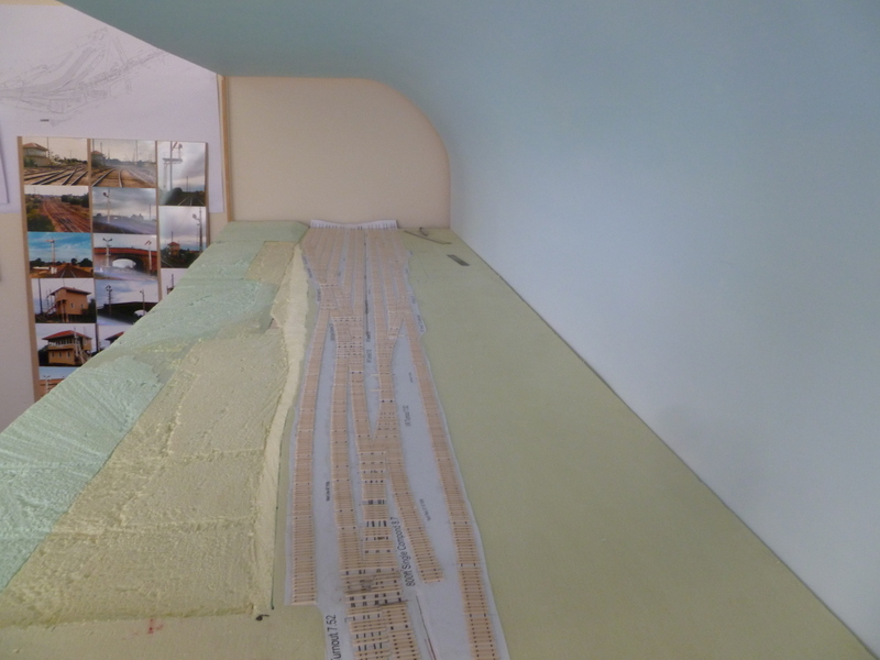
Once the desk is done I planned to get right into rail laying. I hopefully my etching skills will be ready and my 3d parts as well. I plan to start with the straight track and then moving onto the turnouts. I will also be starting work on the brick/stone road bridge as this needs to be done so i can get the landscape heights right.
2013 had many learning curves, slow progress on the layout but I’m hoping in 2014 will show the fruits of 2013. I would like to wish everyone a Merry Christmas and a happy new year.

Friday 15 November 2013

My first etching


Well I got to do my very first etching the other day. It went fairly well, there are few things to work on, but it was a great first effort. I wont go into too much detail on the process, as I want to be able to get all the steps 100% right first.

The main thing that went wrong in this test was that the top pattern moved by about 0.5 mm to 1mm in the exposure process, which lead to the holes not being perfect. I felt I got the etching time right, however I do need to build an improved etching tank. I will need to make one that will be able to take A4 size brass sheets. I’ve added some photos below of what went on. You can see in the final shots of the brass how the topside is not right, but is something that I can work on. I used .25mm brass sheet in this test.

I hope I will be able to do a more in depth blog on the whole etching process soon.


Monday 14 October 2013

October Update

Good news Bendigo A box survived the move! bad news no work has been done on the layout since the move, but this will change very soon.  Well the house move went very well nothing was broken which is always nice.  Now that the whole house is nearly all painted i can start to think about doing some work on the layout. First thing is i plan to build a new modelling desk in the spare room. This should be alot better than the old round table i was using. I will post about this new desk soon, as its not yet built but have planed it in my head.  The one thing about painting a house is that it gives you lots of thinking time.  Here are some changes that i will be making to make the layout better.

1. I have removed the curved backdrop.  I have done this for two reasons, i need better access to the back for landscaping the foam. Should have shape the foam before gluing down. The other is ive change the way the layout will be built in the shed. The curved back drop will be apart of the internal frame work of the shed. More on that some other day.


2. Etching, the cost of etching is very high so im going to give it a try myself. One problem using a etching company is that they need a minimum size of a A4 sheet. So when testing parts you have to fill up a whole sheet first with parts to test. This is were i have lost a lot of time designing parts to make a full sheet.  About half the parts i was going to etch that need etching to be spot on, im now going to get 3D printed. This will be easier to build these bits as i will not need to worry about etching tolerances and fold lines etc.  The parts i will etch myself are going to be the sleeper plates.  I will post later on DIY etching. It is a long progress and will take a few goes to get right.

3. I have change the layout width from 700mm to 800mm. This will hopefully help balance the layout. I want to get the scenery to track ratio right!

4. I have done a draft plan of the whole layout in the shed with mainly the bench work shape and walkway widths done. I have also worked out the locations of the stations, yards and infrastructure

Sorry that progress has been slow but hopefully things will start to pick now. Im hoping track work is only just around the corner.

Friday 31 May 2013

On the Move


Well its been a huge few months in our personal life with the sell of our house and a purchase of our new home on a very nice 11.5 acres up in Gembrook.  So Bendigo has found its new home, just need to build the shed for it to go in.  So with all the fun of selling the house, no work has happen to Bendigo, but my brain has still been coming up with some new ideas for the layout. 

With the pending move not much work will happing on the layout but more behind the scenes stuff will.  I really need to finish off the etches and than make up the final test parts for all the track work.  Some parts will require some moulding to be done so I will need to learn how to do that. For that will be my main focus of work. Like everyone I also have a pile of half done models that need to be finished off so will try and get them done and posted up onto the blog.

For now I thought I might post just a couple of before and after photos of Bendigo A Box area. The before photos (taken in the 80's) are from stationpast.net and have been used with permission and the after photos were taken by me in Jan 2013. Stationpast.net has a large range of photos of stations and yards from the past all over Australia. I also have some photos taken in the 60's but will save them to compare with when ive built more of the layout.
Click to make bigger

Bendigo A Box
Same shot but taken back more
Old site with the concrete
steps still in place


Taken from road overpast looking
towards Bendigo (left side of bridge)
Looking the same way towards Bendigo
but on the right hand of bridge
Towards Bendigo A Box
 
Towards Melbourne


Top end of yard looking
towards Melbourne
Note the buffer stop still there
from above photos


Same of the photos don't match up very well but it gives you an idea of the area anyway. Thanks for looking and im sorry work has been slow but it will all be all worth it in the end. If you have any photo of Bendigo in the 50's, 60's and 70's please let me know at bendigonscale@live.com.au

Wednesday 3 April 2013

March Update

Well March has been and gone and not much was done on the layout. I had planned to finish off the etching design work and get a test run done, but my PC had other ideas. After the motherboard failed I had no PC for 3 weeks.  With that and other things work etc, I only got around to doing one end of the end plates.

These are fairly easy to make by using 12mm ply wood. The trick is to make two a once so you have one already to go for the next module.  To make the end boards I clamped the ply to the frame and than traced the outline of the land onto the wood.  I than cut and sanded the ply to match the land form. Once I was happy with shape I than glued and screwed the ply onto the frame the same way I did the curved brackets.  There was a small gap between the ply and the foam so I used a little bit of wood filler in the gap and than sanded it back. Once dry the sleepers than can be laid over the top.


With my PC now back im hoping I can finish off these etches and than get into track laying. Looking forward to making and detailing the turnouts and compounds which should provide some really good post. 

Saturday 9 February 2013

Landscaping Bendigo

As said in my last post i wanted a slight change in what was doing. After laying all those sleepers i wanted to do something a abit different on the layout.  So i went about landscaping the front of the module. This is important as before i can my the end plates i needed to do the contour land so i can match the end plates to it. I also need to do the end plates before i can lay the rail.
I was lucky enough to find a VR map of bendigo with survey points on it. The map was done in 1929 so its a little out of date but it was going to give me a great reference on how it was. I than set a datum point on the map which was the height of the rail bed and than worked off that to get the slopes of the land. I than scaled it down to match my layout and wrote down the depth next to each point on the foam. I was also able to use the photos i took of the area to help with how the land flowed.  I will put some before and after shots up in another post. There are many ways to workout how to get the depths right, but this is how i did it.  
 
Click on photos to make them bigger
Working from the front going into the layout i slowly pushed a metal ruler into the foam to the correct depth.


From that i than cut out channels in the foam to the depth front to back. Once that was done i than used saws and hacksaw blades to cut the foam out. I found this a great way to get the slope right. Using a hacksaw blade was really good due to its fine teeth and i was flexible to match the slope needed.


At the front of the module there will be some houses along the street front so l left the land flat but it does slope down right to left to about the middle of the module were there is a small creek/drain and than goes up left to right. From there going towards the railway the land follows the same contours but also has a slope that goes up towards the yard and than there is a step embankment to go up onto the rail height. Here are some progress shot that happen along the way.


Im really happy how it has worked. It took some time to do but that was due to been careful as i wanted to get it as close to the real thing.  I still have to do the back but it has a different shape than the front and doesn't go down as deep as the front.  I still have to smooth off some areas and finish of road bridge end but it has been a nice change in layout construction. In these photos you can see the steep embankment going up onto the yard. Having some land shape really does change the look and feel of the layout and im really looking forward to when the scenery goes down and adds colour to it all.


Wednesday 6 February 2013

Drilling holes for the throw bar

I thought i would give a quick how to on drilling the holes for the throw bar wire for the turnouts. I plan to use servo motors to move the the turnout blades. This is done by mounting the servo under the layout with a strong wire coming up through the baseboard and foam and than connecting to the throw bar of turnout.  I good example of this is on the Tam Valley depot website. When it comes to installing the servos i will do a full how to but for now its important to drill the holes before the turnout is laid on the layout.

Its really easy to do but you do have to be careful when drilling through the foam as its really easy for the drill bit to move about. Down below are the steps.

1. Mark were to drill, you need to drill in the centre of the turnout where the throw bar is.
2. Drill a 3.5mm pilot hole slowly. Its good to set the drill on a slow speed. Drill all the way through the foam and baseboard.
3. Drill the final hole of 6.5mm. Once again drill slowly and be careful when the drill bit graps the baseboard, it can pull down on the drill.
4. Clean up the hole.
1.
2.


3.


When i was laying the sleepers for the turnout i left out the sleepers near the hole as this made drilling easier. You can see in the final photo that one of the sleepers nearly covers the hole that was drilled. There is a space left for a PC sleeper to go in when the turnout is laid. I may also insert a brass tube a later date but this can be done from under the layout.

Ive also be busy forming the landscape which is making the layout look really nice. It adds so much by having hills and valleys. I will share all this in another post very soon.

Tuesday 29 January 2013

Sleepers done


Track gangers have left the site (well for a short break)
 
Well just coming under 4000 sleepers i have finished laying most of the sleepers on the module. Only ones needed to do are the sleepers near the end plates and also near where i have to drill the holes for the throw bar wire to come through. Once the holes are drilled i will than place those sleepers in.  Some of the gaps you will see are also for the PC sleepers.  From all the plans ive been able to use i have laid the sleepers to about 98% as they were in real life. In some areas there may be one or two sleepers that might not be right but this is due to having a scale of 1:160. Im very happy the way it has gone so far. Down below are the photos of the module.  I love the look of the wooden sleepers, the placement and the spacing of them. (Not all in a perfect line, its my pet hate with commercial track it to straight and perfect) Once coloured and scenery is done they will blend in very nicely and look very prototypical. 
Click on photo to make them bigger


Whats next?
Well im a bit track laying out for now, so im going to work on landscaping the area. This will involve getting the right heights of the hills and ditches. Ive been lucky enough to find a plan with contours on it which will help me greatly in getting the land form correct. I will also be working on some more brass etches so i can send off a final test run and i will also start the design work for the brick covert drain and the brick and stone road over bridge.  I plan to make my own brick paper and stone moulds for this.  Once again any one has plans or photos to share that my help email me at bendigonscale@live.com.au